


【Semiconductor etching process】The soul of semiconductors teaches the etching process and the practice of engineers on defective rate problems from 0 to 1(CH5-CH6)
Aug 28, 2025
Leave a message
CH5. Types and applications of Plasma, principles of DryEtch
Types of plasma
Classification by mode of generation
DC plasma = Gas is charged between the anode and cathode of two parallel plates to produce plasma by applying a voltage.
DC plasma heating = secondary electron emission.
Sheath voltage=Cathode:2000 + Vp / Anode:Vp.
Sputtering or Etching and other Process
If one pole is an insulator→ the insulating electrode is charged to cancel the breakdown voltage→ AC voltage is required.
RF plasma = Plasma is generated using radio frequency (RF) properties that alternate periodically from positive and negative electrodes (causing gas collisions). For sputtering or etching of insulators.
Compared with DC plasma, the ionization speed is 10~100 times faster.
Plasma can be generated even if the electrode is not a conductor.
When an electric field is formed by electrodes between two parallel plates, the medium (gas type) and pressure in the cavity are important variables.
Classification by source of origin
RIE (Reactive Ion Etching) = Plasma source using two parallel plate electrodes.
The wafer is placed on the side of the RF voltage → RIE mode → forms a DC negative self bias voltage → to achieve anisotropic etching.
The wafer is placed on a ground electrode → in Plasma Etching mode → achieve isotropic etching.
MERIE = a modified version of RIE that applies a magnetic field to the plasma region → increases the probability of ion formation and obtains high-density plasma for etching.
Compared to RIEs, the ionization efficiency is higher and the process can be operated at low pressures.
HDP (High Density Plasma) = Plasma generation and ionic energy regulation can be controlled independently.
For example:ECR,TCP,ICP,Helical Plasma.
Classified as for temperatures:
Cold Plasma = Used in semiconductor manufacturing
Thermal Plasma = Used in metal cutting
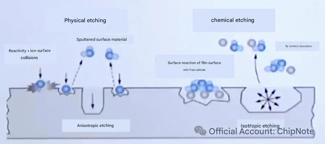
Dry etching = chemical etching caused by free radicals + physical etching caused by ions
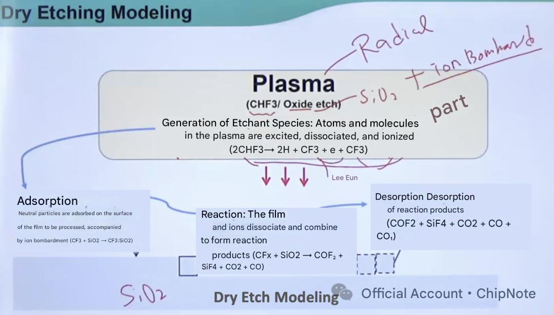
Principle
The gas involved in the chemical bonding is introduced into the cavity → an RF voltage is applied to initiate the generation of plasma
Gases that enter the plasma state are activated into forms such as ions, radicals, electrons, atoms, etc
Free radicals are etched by chemical bonding/ions are stripped of atoms by physical collision
Plasma Etching = Chemical + Physical ⇒ RIE
The residual gases generated during the chemical bonding process are discharged to the outside by a vacuum pump
CH6. Understanding and requirements of dry etching methods
Dry etching method
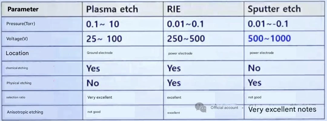
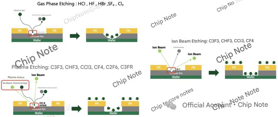
(3→2→1: Chemistry, Isotropy, High Pressure & Low Energy / 1→2→3: Physics, Anisotropy, Low Pressure & High Energy)
1.Plasma Etching
2.Reactive Ion Etching, RIE
3.Sputtering Etching
Factors affecting the dry etching process
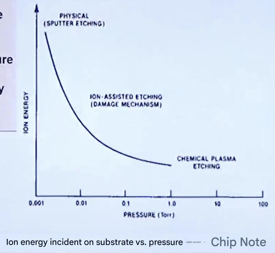
1)Process Pressure= Low pressure: physical etching (sputter etching) / high pressure: chemical etching (plasma etching) Between low pressure and high pressure: chemical + physical simultaneous action
RF Power=Affects plasma density → The higher the power, the higher the etch rate (faster)
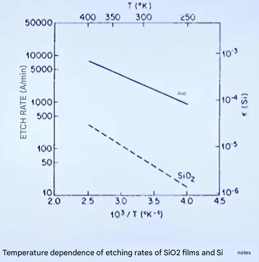
Substrate Temp=The higher the temperature, the higher the etch rate (faster)
4.Process Gas
5.Gas Flow=Determines the residence time of a chemical species → The longer the residence time, the higher the etch rate
Requirements for dry etching process
1.High mask/film selection ratio
2. anisotropy
3.High etch rate (productivity) – Etching of Cu/Pt is problematic → Cu is using the Damascene process
4.High uniformity – its importance increases as wafer size increases
5.Low Damage – As device integration increases, the importance of low plasma damage increases
6.Cleanliness – Yield – Wafer surface detachment occurs during etching, so it's important to keep it clean
7.Mask is easy to remove/safe
Effects of carbon/fluorine ratio
The C/F ratio is related to the amount of polymer generated during plasma etching, and therefore also affects the etch rate.
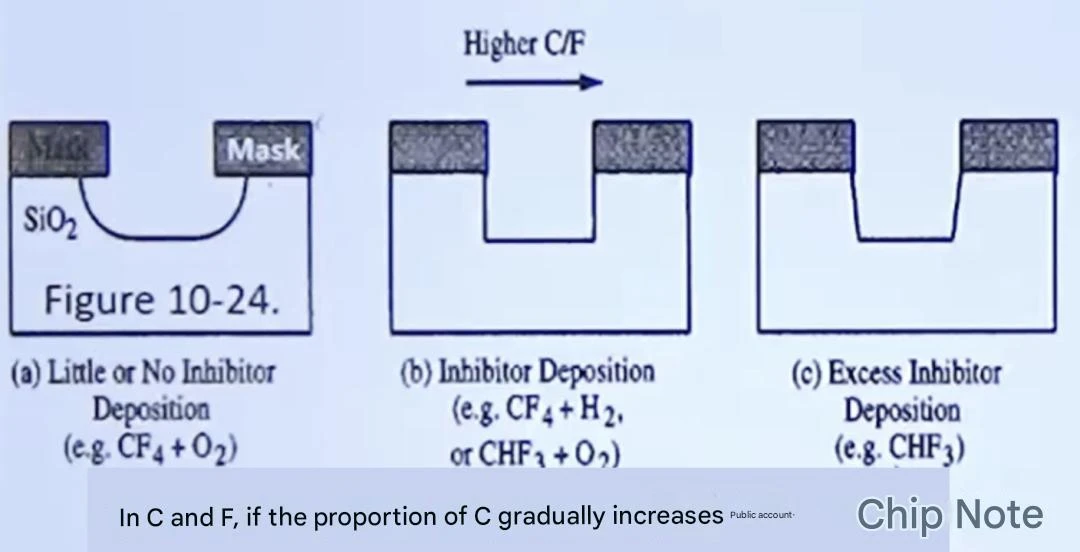
When the proportion of C increases, an inhibitor is generated.
Inert gases like Ar⁺ are used to remove the inhibition layer at the bottom of the pattern (ion bombardment etching) due to the absence of chemical reactions.
The inhibition layer on the sidewall is removed using O₂ or CF₄.
A decrease in the ratio of F/C gases increases the selection ratio of SiO₂ to Si.
The inhibitory layer is sometimes intentionally induced to achieve anisotropic etching.
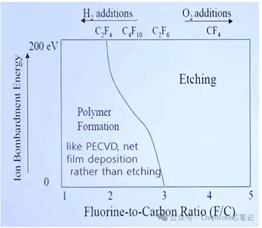
• Low F/C (high C content) → deposits (forms) an inhibitory layer
• Adding H₂ → to generate HF, which removes F, reduces the F/C ratio, and slows down the formation of SiF₄, resulting in a decrease in etch rate
•" → Improve the SiO₂/Si selection ratio
•Sufficient H₂ → Due to the lack of sufficient O₂ on the Si surface, Si is not etched ⇒ deposited occurs
0010-13264 5200 Tube Robot
Send Inquiry