


Full analysis of moving parts of semiconductor equipment
Dec 09, 2025
Leave a message
1. Detailed explanation of core motion control components
In semiconductor manufacturing equipment, moving parts are at the heart of enabling nanometer-level precision operations. From the rapid response of pneumatic components to the precise control of electric systems, each component plays an irreplaceable role in key links such as wafer transfer and lithography alignment.
1)Pneumatic components: high-speed and clean power source
Pneumatic components are powered by compressed air, and with millisecond-level response speed and zero pollution characteristics, they occupy an important position in wafer handling, valve control and other scenarios.
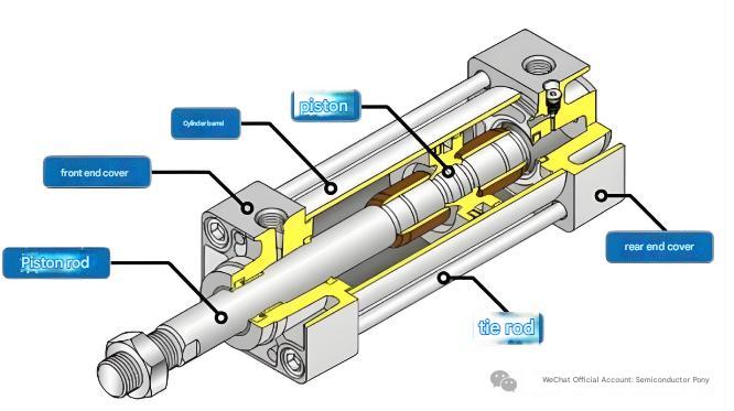
As the main actuating element, the cylinder is divided into three categories: standard cylinder, thin cylinder and guide rod cylinder according to structural differences.
The standard cylinder stroke can reach 1 meter, and the thrust range is 5-500N, which is suitable for linear drive of wafer transfer robotic arms;
TIN Chamber Assy
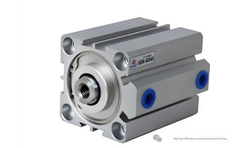
The thickness of the thin cylinder is only 1/3 of that of the traditional model, which is outstanding in vacuum chambers with limited space.
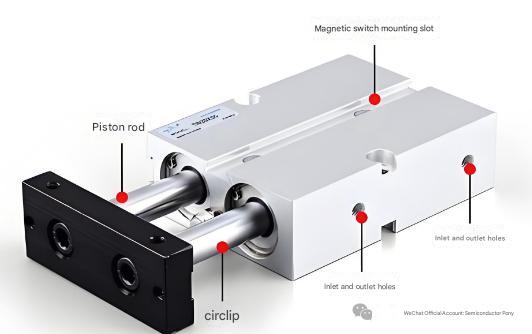
The guide rod cylinder eliminates radial deviation through the built-in guide shaft, and the repeat positioning accuracy reaches ±0.02mm, which is often used for precision feeding of photoresist coating equipment.
The performance of the pneumatic valve directly determines the response speed of the system. The Naboc X4V-XPVMT-32 pneumatic valve features a V-stack spool design with a nano-diamond-coated sealing ring to achieve a 10ms open/close response and 2 million leak-free runs (ISO 13849-1 PLd compliant). Its integrated MEMS pressure sensor monitors valve cavity pressure in real time and outputs predictive maintenance data via the PROFINET interface, reducing equipment failure rates by 40%.
2)Motorized components: the core driver for nanoscale positioning
0021-02983 TXZ Inner Shield
The electric components achieve sub-micron motion control through the combination of motors and precision transmission mechanisms.
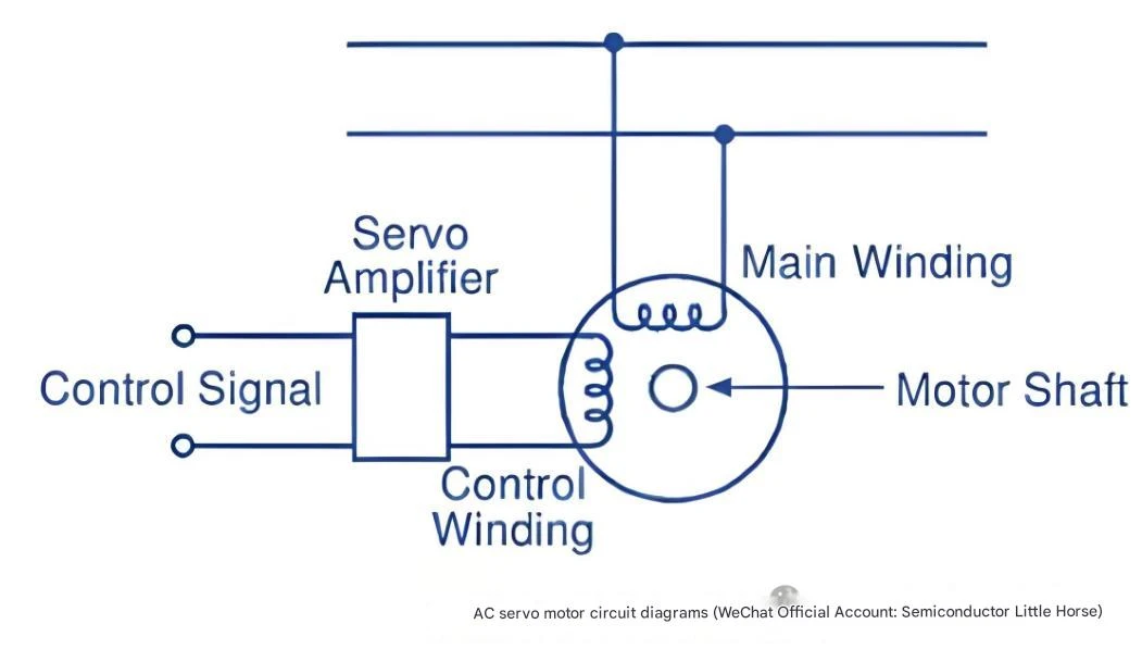
Servo motor as the mainstream choice, taking ASML 4022.436.02934 model as an example, it adopts rare earth permanent magnet and coreless cup winding design, rated speed 3000rpm, torque fluctuation ≤ 0.5%, with AMAT 0190-17056 drive, can achieve position control with 0.1nm resolution. In the application of lithography machine workpiece, the motor controls the dynamic following error within 3nm through a double-sided synchronous drive structure.
The linear motor eliminates the intermediate transmission link and directly outputs linear motion. Han's Motor's HMDR series torque motors have a peak thrust of 20,000N and an acceleration of 20g, achieving high-speed scanning of 600mm/s in the wafer inspection platform. The Delta CMC-MH2P11 controller controls multi-axis synchronization through the EtherCAT bus (125μs cycle) to achieve a repeatable positioning accuracy of ±0.01mm in chip transfer machine applications.
3)Mechanical components: the physical basis of high-precision movement
Mechanical components are the ultimate guarantee of motion accuracy.
In the guide rail system, the cross roller guide rail is in contact with the track through the roller, with a rigidity of 200N/μm, which is suitable for the mask table of the lithography machine. The ball guide is used to achieve high-speed motion with point contact, with a speed of up to 120m/min, and is often used in wafer transfer systems. The parallelism error of THK HSR series rails is ≤ 0.01mm/m, and the vibration amplitude is controlled to 1-3nm (in line with the vibration standard of lithography equipment) with preload adjustment technology.
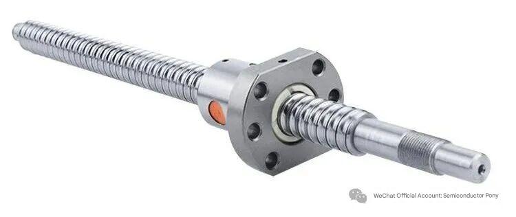
The ball screw converts rotary motion into linear motion, and the positioning error of the C3 precision screw is ≤0.003mm/300mm, and the lead error is ≤ 5μm/m. The planetary roller screw improves the load-bearing capacity through multi-roller contact, and has a lifespan of up to 100,000 hours in the heavy-duty wafer handling robotic arm. It is worth noting that the lead screw selection needs to meet the length-to-diameter ratio of ≤100, and when the stroke exceeds 1 meter, fixed supports at both ends are required to avoid the impact of resonance.
4)Sensing system: Nerve endings for real-time feedback
The sensing system acts as the "eyes" of the device, providing precise position feedback for motion control.
The scale achieves nanoscale measurement through the moiré stripe principle, and the Heidenhain LS 487 scale has a resolution of 0.01μm and a cumulative error of ≤3μm in a 300mm stroke. The "absolute" readhead uses a "reference point" that does not require reference point regression, and the position information can be obtained when the power is turned on, greatly reducing the start-up time of the device.
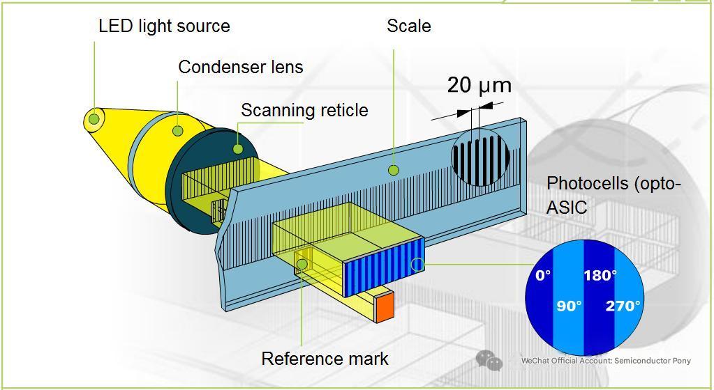
The encoder is directly connected to the motor shaft to monitor the speed and position in real time. Renishaw's RESOLUTE series encoders use optical scanning technology to maintain an angular accuracy of ±0.01° at 10,000 rpm. In a vacuum environment, the magnetostrictive sensor relies on the advantages of non-contact measurement to feed back the wafer stage position data to the control system at a frequency of 10kHz to ensure sub-nanometer synchronization during the exposure process.
Motion control interaction mechanism
Motion control of semiconductor equipment is a complex system engineering, from control system instructions to actuator actions, involving the coordinated transmission of electrical signals and pneumatic signals. Understanding this interaction process is crucial for optimizing equipment performance and troubleshooting.
1)Signal transmission path analysis
The complete motion control process begins with the command of the upper computer, which is processed by PLC and transmitted in two ways: the digital signal is sent to the servo drive through the EtherCAT bus to control the motor movement; The analog signal drives the solenoid valve to adjust the state of the pneumatic components. Taking the lithography machine wafer table as an example, Delta XPCIE1032H motion control card as the core hub, and its MotionRT750 real-time core compresses the control period to 50μs to achieve 16-axis synchronous control (position synchronization error ≤ 10ns).
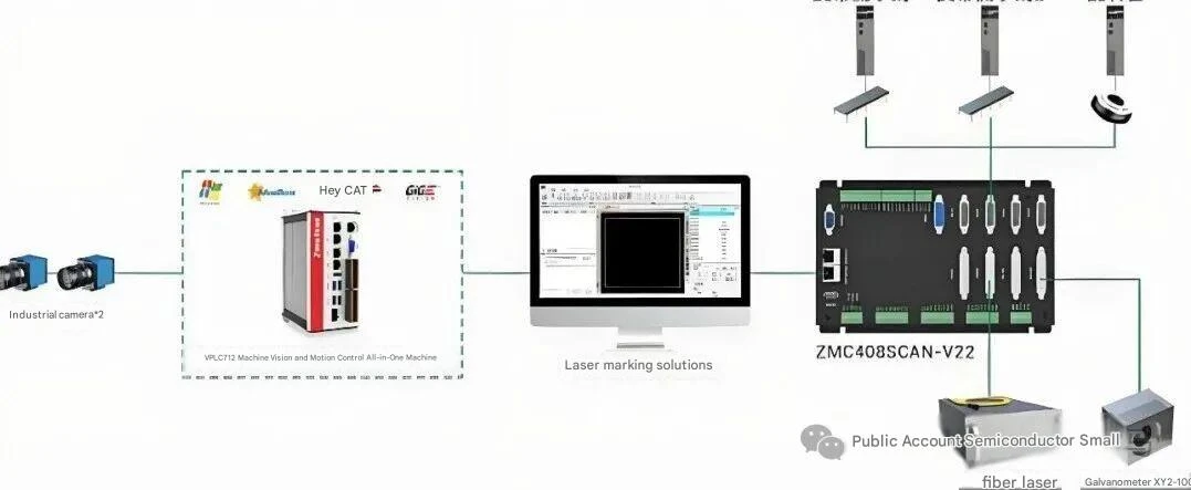
The feedback link forms the key to closed-loop control. After the grating scale and encoder data are preprocessed by the FPGA, they are transmitted back to the controller via the SERCOS III protocol, and the sampling frequency reaches 2MHz. When the position deviation is detected exceeding the threshold, the system starts the feedforward compensation algorithm to correct the error in real time through the piezoelectric ceramic driver, and the response time is < 1ms.
2)How components work together
The synergy of electrical and pneumatic components is reflected in the precise matching of signal timing. In the wafer transfer scenario, when the robotic arm approaches the target position, the proximity sensor (detection distance 1-5mm, repeatability 1%) sends a trigger signal, and the PLC immediately cuts off the cylinder air supply, and at the same time starts the brake mechanism of the servo motor to achieve shock-free docking. This mode of "pneumatic rough positioning + electric fine adjustment" shortens the wafer handover time to 0.5 seconds and controls the breakage rate to less than 0.03%.
The transmission of pressure signals also requires precise coordination. The reaction chamber pressure control of AMAT Endura PVD equipment adopts a hierarchical strategy: the coarse adjustment stage is achieved by means of a Naboc pneumatic valve in the range of 100-1000 mTorr with an accuracy of ±5%; The fine-tuning stage switched to an electric proportional valve, and the pressure was stabilized at ±0.1mTorr by PID algorithm, ensuring that the film uniformity of sputter deposition was > 99.5%.
3)Typical scenario application cases
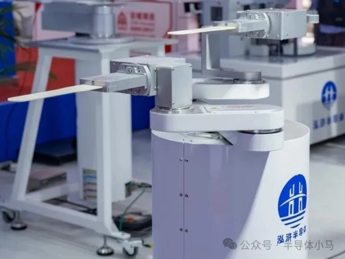
Wafer transport systems are the culmination of motion control technology. The dual robotic arm system shown in the figure below adopts a "master-slave collaboration" architecture: the main arm is equipped with a vacuum suction cup (suction force is adjustable from 0.5-2N), and the X/Y axis movement is realized through the crossed roller guide. The slave arm is equipped with a six-degree-of-freedom trim platform that utilizes a piezoelectric ceramic driver to compensate for ± 10μm alignment deviation. When the system is operated in a Class 1 cleanroom, it produces < 0.1 particles/ft³, meeting the requirements of the SEMI F47 standard.
The lithography positioning scene shows higher precision requirements. The workpiece table of the ASML TWINSCAN NXE:3400B lithography machine adopts magnetic levitation drive, and the X/Y axis motion is monitored in real time by laser interferometer (resolution 0.01nm), and with 16 sets of gas spring vibration isolation system, the ground vibration interference is attenuated to less than 1nm. During the exposure process, the mask and wafer stages move in reverse at 5G acceleration, and the synchronization error is controlled at the level of 60 picometers (less than the diameter of the silicon atom).
Technical characteristics and requirements
The unique nature of the semiconductor manufacturing environment places stringent demands on moving parts that far exceed those of ordinary industrial equipment. From nanometer-level positioning accuracy to ppb-level cleanliness control, every metric is the ultimate challenge to engineering technology.
1)Performance metrics in extreme environments
Positioning accuracy is the core indicator of semiconductor equipment. According to SEMI standards, the repeatability accuracy of the wafer stage of the lithography machine should be ≤± 3nm, while the flatness error of the etching machine should be < 5μm/300mm. To achieve this, the motion system needs to control six degrees of freedom at the same time: X/Y axis positioning error, Z-axis perpendicularity, θx/θy/θz rotation error, of which θz (yaw) needs to be controlled within 0.5 μrad.
Cleanliness requirements are equally stringent. All moving parts must meet the ISO Class 1 standard, which is < 1 particle size ≥ 0.1 μm per cubic foot of air. For this purpose, the bearings are coated with solid lubricants (such as molybdenum disulfide), the gear drive is changed to synchronous belt drive, and the motor windings are impregnated with special resins to prevent volatile production. ON Semi NCS32100 inductive sensors even fully seal the PCB board to ensure no particles are released during 1000 hours of operation.
2)Comparison of pneumatic and electric drive modes
Pneumatic and electric drives complement each other in semiconductor equipment. The initial cost of the pneumatic system is only 1/3 of that of the electric solution, and the response speed is 5-10 times faster, which is obvious in short-stroke scenarios such as wafer loading and unloading. However, its positioning accuracy is affected by air pressure fluctuations (±0.5%) and the energy consumption is high (the efficiency of the air compressor is only 30%). The electric system achieves a speed stability of ±0.1% through closed-loop control, which is irreplaceable in precise scenarios such as lithography alignment, but complex cable management increases the difficulty of system design.
|
Performance indicators |
Pneumatic drive |
Electric drive |
|
Response time |
5-10ms |
10-50ms |
|
Positioning accuracy |
±0.05mm |
±0.001mm |
|
Cleanliness |
ISO Class 1 |
ISO Class 10 |
|
Energy consumption (continuous operation) |
1.2kW |
0.3kW |
|
Maintenance intervals |
6 months(Replace Sealing) |
2年(Bearing lubrication) |
In practical applications, hybrid drive solutions are gradually emerging. Delta's CMC-MH2P11 controller supports the "pneumatic fast forward + electric precision positioning" mode, which can complete the handling of 500mm stroke and ±2μm alignment in 1 second in the chip transfer machine, and increase the overall efficiency by 40%.
3)Future technology development trends
With the advancement of 3nm and below processes, motion control technology is developing in the direction of "higher precision, lower energy consumption, and more intelligence". XPCIE2032H motion control card adopts a 254-axis synchronous control architecture, shortens the EtherCAT communication cycle to 125μs, and compresses the trajectory planning time from 20ms to 5ms with AI adaptive algorithms. The new piezoelectric ceramic motor is expected to achieve picometer-level control in the mask alignment of EUV lithography machines through nanoscale steps (0.5nm) and 1000Hz response frequency.
Material innovation is also worth paying attention to. The application of silicon carbide ceramic rails (friction coefficient 0.001) reduces wear rates by 80%, while graphene-coated lead screws can last up to 3 times longer than conventional products. These technological breakthroughs not only improve equipment performance but also provide a new path for the sustainable development of semiconductor manufacturing.The moving parts of semiconductor manufacturing equipment, like the internal gears of precision watches, interpret the ultimate pursuit of industrial civilization in millimeters. From the rapid response of pneumatic components to the nanoscale dance steps of electric systems, every technological breakthrough drives continuous breakthroughs in chip manufacturing. As we marvel at the power of 5nm chips, one should not forget the motion systems that silently operate in the cleanroom – they are the true dancers of the microcosm.
Send Inquiry